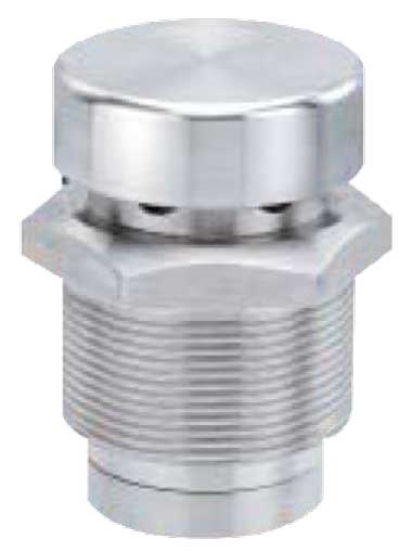
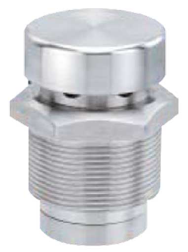
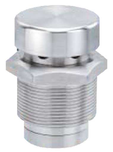
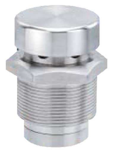
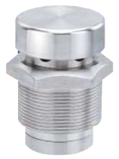
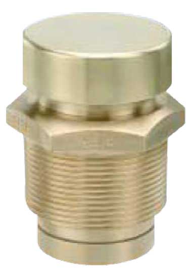
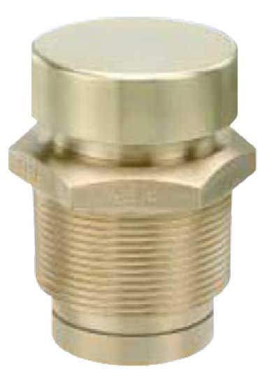
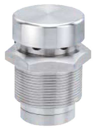
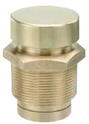
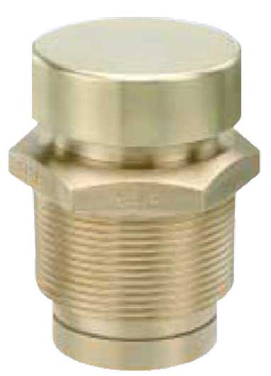
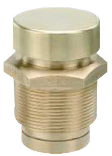
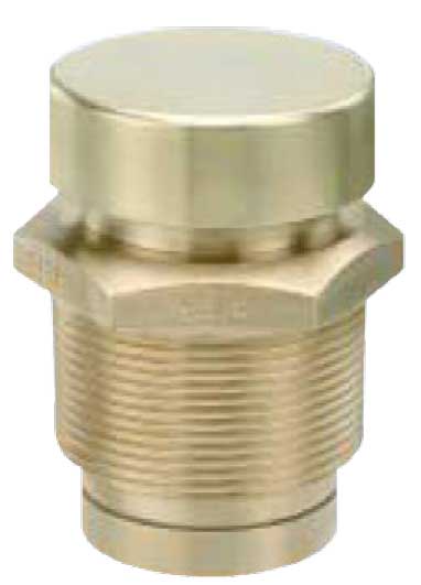
Anti-Vacuum Valves

The Fig 568 Anti-Vacuum Valves are used to protect drying cylinders, calorifiers and tankers from collapse due to internal vacuum.
They are also used on steam systems to assist condensate drainage and to prevent suction of contents from vats. Vacuum valves are normally fitted vertically at the top of the vessel or pipeline that is being protected. Horizontal revolving cylinders however should have a Fig 568 fitted at each end diametrically opposite of each other.
The Operation of valves in service should be checked every twelve months.
Construction
The Fig 568 is supplied with PTFE or Viton to metal seating design which provides excellent seat tightness.
The valve is approved by the Water Research Centre for use on potable water. The valve head which is normally held against its seat by system pressure is set to open at a vacuum pressure of 50mbar. A dust cap prevents the direct entry of foreign matter.
The strengthened body complete with taper thread ensures a tight seal between the vessel and valve whilst maintaining the integrity of the seat seal.
Sizing
The capacity of an anti-vacuum valve should be equal to or greater than the rate of the vacuum formation in the vessel being protected.
To assist selection reference should be made to BS 853 cl 10.3 or to the capacities of the Fig 568 tabulated below.
| Air Std.Litres/Sec | ||||||
|---|---|---|---|---|---|---|
| Vacuum Pressure mbar | DN15 | DN20 | DN25 | DN32 | DN40 | DN50 |
| 250 | 2 | 5 | 19 | 21 | 32 | 52 |
| 500 | 3 | 9 | 17 | 32 | 53 | 71 |
| Size DN |
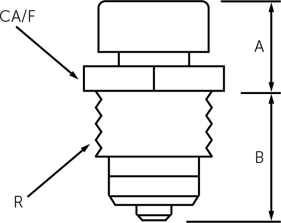
R BSPT |
A MM |
B MM |
C MM |
|---|---|---|---|---|
| 15 | ½ | 23 | 35 | 24 |
| 20 | ¾ | 25 | 36 | 30 |
| 25 | 1 | 27 | 39 | 36 |
| 32 | 1¼ | 33 | 43 | 46 |
| 40 | 1½ | 39 | 53 | 53 |
| 50 | 2 | 37 | 57 | 65 |

